Custom shape
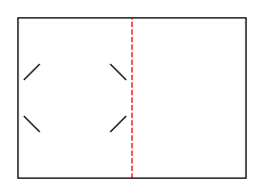
Custom shape with creases
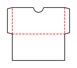
Folding carton with a glue flap and one tuck flap each at the top and bottom; both tuck flaps are attached to the front.
Opens the online editor with this template. Try it without payment details; export with Pro.
There is no vector preview for this template.
- Template
- Custom shape with creases
- Category
- Custom shape
- Dimension reference
- Nominal size
- Default dimensions
- –
- Parameters
- 13
- Version
- v1
- Template ID
- custom.polygon
Dimensions and limits
This template has no fixed overall dimensions; you define the contour in the editor.
Parameters of this construction
13 parameters with default value and limits, adjustable in the editor.
| Parameter | Default | Range | Note |
|---|---|---|---|
Corner radiuspolygonCornerRadius | 3 mm | 0–20 mm | Radius at all contour corners with at least a 5° direction change; crease line ends remain sharp. |
Crease 1 from pointpolygonCrease1From | 0 | 0–500 | Number of the contour point where the crease line starts (1 = first contour point); 0 = no crease line. |
Crease 1 to pointpolygonCrease1To | 0 | 0–500 | Number of the contour point where the crease line ends; the line must lie within the contour and must not cross another crease line. |
Crease 1 fold anglepolygonCrease1Angle | 90° | -180–180° | Fold angle of the crease line: positive inward, negative outward; 0° remains flat. |
Crease 2 from pointpolygonCrease2From | 0 | 0–500 | Number of the contour point where the crease line starts (1 = first contour point); 0 = no crease line. |
Crease 2 to pointpolygonCrease2To | 0 | 0–500 | Number of the contour point where the crease line ends; the line must lie within the contour and must not cross another crease line. |
Crease 2 fold anglepolygonCrease2Angle | 90° | -180–180° | Fold angle of the crease line: positive inward, negative outward; 0° remains flat. |
Crease 3 from pointpolygonCrease3From | 0 | 0–500 | Number of the contour point where the crease line starts (1 = first contour point); 0 = no crease line. |
Crease 3 to pointpolygonCrease3To | 0 | 0–500 | Number of the contour point where the crease line ends; the line must lie within the contour and must not cross another crease line. |
Crease 3 fold anglepolygonCrease3Angle | 90° | -180–180° | Fold angle of the crease line: positive inward, negative outward; 0° remains flat. |
Crease 4 from pointpolygonCrease4From | 0 | 0–500 | Number of the contour point where the crease line starts (1 = first contour point); 0 = no crease line. |
Crease 4 to pointpolygonCrease4To | 0 | 0–500 | Number of the contour point where the crease line ends; the line must lie within the contour and must not cross another crease line. |
Crease 4 fold anglepolygonCrease4Angle | 90° | -180–180° | Fold angle of the crease line: positive inward, negative outward; 0° remains flat. |
Assembly
Pre-break the blank along all creases. Glue the glue flap to the inside of the opposite wall and lay the carton flat. Erect for filling, fold in the dust flaps, and insert the tuck flaps.
Grain direction
no recommendation (check)
Reference note
No external reference classification stated in the catalog.
Labels such as “similar to FEFCO” or “ECMA family, unconfirmed” are for orientation only. The templates are our own constructions; an assignment to a standard code is unconfirmed and not a trademark claim.
Frequently asked questions about this template
Which contour does the starting example show?
The point list is 0 0; 120 0; 120 160; 60 200; 0 160 in millimeters. It describes a gable-shaped card. The starting corner radius of 3 mm rounds the contour. The measured bounding box is therefore slightly lower than the highest unrounded point coordinate of 200 mm.
How are crease lines entered?
Each line has a start point number, end point number, and fold angle. Numbers refer to the entered contour sequence, starting with 1. Zero disables the line. Up to four crease lines are supported. The ends must connect suitable contour points; lines outside or along the outer edge are invalid.
What does the sign of the fold angle mean?
Positive angles fold inward, negative angles outward. Zero degrees remains flat. The sequence follows the crease numbers. These settings belong to folding semantics and do not replace a physical test. Especially with multiple creases, check that the entered sequence suits your intended assembly and target board.
Is my contour compensated when I change material?
No. The fixed point contour is the final dimension here; the model uses no material compensation. A material profile change therefore does not confirm a new fit. If the construction needs its own variable dimensions and expressions, a template package is the appropriate approach. Test the fixed contour with the intended material thickness.
What does the function take from a reference dieline?
The code function CustomPolygonV1.input takes the largest closed outer contour and up to four straight crease lines with direction. Holes and interior cuts are not transferred. Crease ends must fit on the contour; curves are flattened. These limits distinguish the custom shape from an unchanged imported reference dieline.
Related templates
Customise the Custom shape with creases in your browser
Set dimensions and material, review findings and export print-ready as PDF, SVG or DXF.